

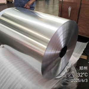
8011 Aluminum Foil for Capacitors
| Ọja | 8011 Aluminum Foil for Capacitors |
| Ibinu | O, H18 |
| Sisanra | 0.005–0.02 mm |
| Ìbú | 100–1000 mm |
| Dada | Pẹkipẹki, mọ dada |
| Awọn ohun elo | Electrolytic capacitors, Awọn ẹya ẹrọ itanna, capacitor foil processing |
1. Isọniṣoki ti Alaṣẹ
8011 Aluminum Foil for Capacitors is a specialized aluminum foil used in selected capacitor applications where controlled electrical, darí, dada, and electrochemical properties are required.
As an 8xxx-series aluminum alloy, 8011 contains controlled amounts of iron and silicon, which influence its strength, rolling behavior, microstructure, ati dada abuda.
In aluminum electrolytic capacitors, aluminum foil serves as the electrode material.
For the anode, the aluminum surface undergoes electrochemical etching to increase its effective area, followed by anodic formation that produces a thin aluminum oxide dielectric layer.
The resulting surface structure has a direct influence on capacitance, voltage capability, leakage current, and overall capacitor performance.
The suitability of 8011 foil therefore cannot be judged by alloy designation alone.
Gbona kemikali, bankanje sisanra, irunu, ọkà be, Didara dada, etching response, and formation behavior all need to match the capacitor manufacturer’s process.
2. Kini Ṣe 8011 Aluminum Foil for Capacitors?
2.1 Definition of 8011 Capacitor Aluminum Foil
8011 capacitor aluminum foil is a thin, rolled aluminum product manufactured from AA8011 alloy and processed to meet the specific requirements of capacitor production.
8011 jẹ ti awọn 8xxx aluminum alloy series and is primarily an Al-Fe-Si alloy.
Compared with high-purity 1xxx-series aluminum, 8011 contains higher levels of alloying and impurity elements, which can provide useful mechanical and processing characteristics.
Sibẹsibẹ, capacitor foil is a highly specialized product. Manufacturers must carefully control its chemical composition, metallurgical structure, dada majemu, and thickness to ensure that the foil performs reliably during subsequent capacitor manufacturing processes.
2.2 Role of Aluminum Foil in an Electrolytic Capacitor
In a typical aluminum electrolytic capacitor, the main functional materials include:
- Anode aluminum foil
- Cathode aluminum foil
- Electrolyte
- Separator paper
- Aluminum oxide dielectric layer
The aluminum foil acts as an electrode, while the oxide film formed on the anode surface functions as the dielectric.
The basic manufacturing sequence can be simplified as:
Aluminum Foil → Etching → Formation → Winding/Assembly → Electrolyte Impregnation → Sealing
Among these processes, etching and anodic formation are particularly important because they transform the original aluminum surface into the high-effective-area electrode and dielectric system required by the capacitor.

2.3 Etching Increases Effective Surface Area
A flat aluminum foil has a relatively limited geometric surface area.
Capacitor manufacturers therefore use electrochemical etching to develop microscopic pits, tunnels, or other controlled surface structures.
This process can substantially increase the effective electrode area without proportionally increasing the physical dimensions of the foil.
The capacitance of an idealized parallel-plate capacitor can be expressed as:
C = εA/d
ibo:
- C = capacitance
- ε = dielectric permittivity
- A = effective electrode area
- d = dielectric thickness
Increasing the effective surface area through controlled etching is therefore an important method for achieving high capacitance within a compact capacitor design.
The actual capacitance behavior of an electrolytic capacitor is more complex because it also depends on electrolyte characteristics, oxide-film properties, separator structure, igbohunsafẹfẹ, otutu, and other design parameters.
2.4 Anodic Formation Creates the Dielectric Layer
After etching, the aluminum anode foil undergoes an electrochemical formation process.
During formation, an aluminum oxide film develops on the aluminum surface. This oxide layer acts as the capacitor’s dielectric.
The thickness and quality of the oxide film are closely related to the required formation voltage and capacitor design.
Nitorina, capacitor foil must not only have a suitable surface area after etching; it must also support the formation of a stable and uniform oxide dielectric layer.
2.5 8011 Foil for Anode and Cathode Applications
The requirements for anode and cathode foil are not identical.
Anode Foil
The anode foil generally requires strong control of:
- Etching response
- Effective surface-area development
- Formation characteristics
- Oxide-film uniformity
- Electrical performance
Cathode Foil
Cathode foil serves a different electrical function and may have different requirements for:
- Surface structure
- Itanna itanna
- Etching behavior
- Electrolyte compatibility
- Formation condition
Dajudaju, the specification for 8011 aluminiomu bankanje should be established according to its actual position and function within the capacitor, rather than using one specification for every application.
3. Key Properties of 8011 Capacitor Aluminum Foil
The performance of capacitor-grade 8011 aluminum foil depends on a combination of itanna, darí, metallurgical, dada, and electrochemical properties.
3.1 Controlled Electrical Conductivity
Aluminum provides the electrical conductivity required for capacitor electrodes.
For capacitor foil, conductivity should be sufficiently stable and consistent because excessive electrical resistance can contribute to power losses and affect capacitor performance.
The electrical behavior of 8011 is influenced by its alloy chemistry and microstructure.
Nitorina, controlling elements such as Fe and Si, as well as other metallic impurities, is important during production.
3.2 Suitable Etching Performance
Etching performance is one of the most important characteristics of capacitor foil.
Electrochemical etching creates microscopic surface structures that increase the effective electrode area.
The resulting surface morphology depends on multiple factors, pẹlu:
- Ọja alloy
- Impurity distribution
- Ọkà ti eto
- Crystallographic texture
- Annealing condition
- sisanra bankanje
- Etching chemistry
- Current density
- Iwọn otutu
Fun idi eyi, two aluminum foils with the same nominal alloy designation may not necessarily produce identical etching results.
3.3 Controlled Surface Quality
A high-quality capacitor foil requires a clean and consistent surface.
Potential defects such as:
- Pi pinholes
- Awọn dojuijako
- Deep scratches
- Oil contamination
- Awọn patikulu ti a fi sinu
- Excessive oxidation
- Rolling defects
can interfere with subsequent etching, formation, yiya, or capacitor assembly.
Uniform surface characteristics also help promote more consistent electrochemical processing.
3.4 Excellent Thickness Uniformity
Capacitor foil is often produced in very thin gauges, making thickness control particularly important.
Uniform thickness helps maintain:
- Stable mechanical behavior
- Consistent winding characteristics
- Predictable electrical performance
- Efficient use of internal capacitor space
Thickness variation should therefore be controlled across both the width and length of the coil.
3.5 Good Rolling Performance
8011 must be processed through multiple rolling stages to reach the required foil gauge.
Good rolling performance helps manufacturers achieve:
- Thin final thickness
- Stable gauge control
- Low defect rates
- Consistent surface quality
- Reliable coil production
The rolling process must be carefully coordinated with intermediate annealing and final temper control.
3.6 Appropriate Mechanical Strength and Ductility
Capacitor foil needs sufficient strength to withstand:
- Kikọlu
- Tun pada
- Winding
- Mimu
- Assembly
Ni akoko kan naa, excessive hardness can make the foil more susceptible to cracking or processing problems.
Nitorina, strength and elongation must be balanced according to the capacitor manufacturer’s production process.
3.7 Good Edge Quality
Edge condition becomes increasingly important as foil thickness decreases.
Poorly controlled edges may cause:
- Burrs
- Edge cracking
- Foil tearing
- Short circuits
- Winding problems
Precision slitting and edge inspection are therefore important quality-control steps for capacitor-grade foil.
3.8 Stable Anodic Formation
For anode applications, the aluminum surface must support controlled formation of the oxide dielectric.
A suitable foil should provide a surface and microstructure that allow the manufacturer to obtain a relatively uniform oxide layer under the specified formation conditions.
Formation behavior is influenced by:
- Keyinstristri alloy
- Surface morphology
- Ọkà ti eto
- Etching condition
- Formation electrolyte
- Formation voltage
- Iwọn otutu
Bayi, etching and formation performance should be considered together rather than evaluating the raw foil solely on mechanical properties.
3.9 Microstructural Consistency
The internal microstructure of aluminum foil can strongly affect its electrochemical behavior.
Important factors include:
- Iwọn ọkà
- Grain orientation
- Recystallization
- Intermetallic particles
- Distribution of alloying elements
Controlled microstructure can contribute to more predictable etching behavior and consistent capacitor performance.
3.10 Good Chemical Cleanliness
Capacitor foil is sensitive to contamination because electrochemical processing takes place directly at the metal surface.
Control of:
- Rolling oil residues
- Surface particles
- Metallic contamination
- Oxide contamination
- Isẹri
helps maintain stable processing conditions.
For capacitor manufacturers, cleanliness is therefore a functional requirement rather than merely an appearance requirement.
4. Temper Selection for 8011 Capacitor Foil
Temper selection is an important part of capacitor foil design because it affects foil strength, igbelage, handling behavior, sẹsẹ išẹ, and electrochemical processing.
Unlike heat-treatable aluminum alloys, 8011 develops its mechanical characteristics primarily through cold working and annealing.
For capacitor applications, the required temper should be selected according to the bankanje sisanra, etching process, winding method, and the manufacturer’s formation requirements rather than simply choosing the hardest available condition.
4.1 O ibinu
O ibinu (annealed majemu) is commonly considered when high ductility and good processing flexibility are required.
The annealed condition provides:
- Gongation giga
- O dara ni irọrun
- Low work-hardening level
- Good suitability for subsequent processing
- Reduced risk of cracking during handling and forming
For capacitor foil, these characteristics can be beneficial during high-speed slitting, yikaka, and electrochemical treatment.
Sibẹsibẹ, the exact mechanical properties of O-temper 8011 depend on the final gauge and manufacturing process.
Nitorina, the required tensile strength and elongation should be specified with the supplier.
4.2 H Temper Conditions
H tempers indicate that the material has been strain hardened through controlled cold working.
Compared with O temper, an H-temper foil generally provides higher strength and lower ductility.
appropriate condition depends on the requirements of the capacitor manufacturing process.
For ultra-thin capacitor foil, excessive hardness may increase the risk of:
- Edge cracking
- Foil tearing
- Slitting difficulties
- Winding damage
Nitorina, maximum hardness is not necessarily the objective.
4.3 Temper and Etching Performance
Temper can also influence the foil’s microstructure and crystallographic condition, which may affect its response during electrochemical etching.
Important variables include:
Cold reduction → Annealing → Grain structure → Surface condition → Etching response
Dajudaju, capacitor manufacturers should evaluate temper together with etching behavior and formation performance rather than judging it solely by tensile strength.
5. Typical Specifications of 8011 Aluminum Foil for Capacitors
Capacitor foil specifications are generally more application-specific than those of ordinary commercial aluminum foil.
The buyer should define not only alloy and thickness but also dada majemu, Awọn ohun-ini darí, dimensional tolerances, and processing requirements.
| Paramita | Aṣoju Sipesifikesonu |
|---|---|
| Alloy | 8011 |
| Ibinu | O (Onmealled) or customer-specified temper |
| Aṣoju sisanra | 0.006–0.050 mm (6-50 μm), application-dependent |
| Typical Width | 50–1,600 mm, customized according to production requirements |
| Ifarada sisanra | According to agreed specification; precision tolerance available |
| Dada | Mọ, dan, aṣọ ile, free from harmful oil and surface defects |
| Dada Ipari | Imọlẹ / matte or other agreed finish |
| Edge Condition | Didan, accurately slit, burr-controlled |
| Tensile Properties | According to specified temper, sisanra, and purchaser’s requirements |
| Ilọsiwaju | According to specified temper and thickness |
| Okun Inu Iwọn | Wọpọ 76 mm tabi 152 mm, asefara |
| Òṣuwọn Coil | Customized according to width, OD, and handling requirements |
| Splices | As agreed; normally controlled or restricted for capacitor production |
| Iṣakojọpọ | Moisture-resistant, contamination-resistant export packaging |
6. Etching and Forming of Aluminum Capacitor Foil
Forming and Etching are two critical electrochemical processes that distinguish capacitor foil from ordinary aluminum foil.
Etching increases the effective electrode area, while forming creates the aluminum oxide dielectric layer.
The overall process can be simplified as:
Aluminum Foil → Electrochemical Etching → Cleaning/Surface Treatment → Anodic Formation → Inspection
6.1 Electrochemical Etching
The purpose of etching is to develop a controlled microscopic structure on the aluminum surface.
A simplified process is:
Aluminum surface + electrolyte + electrical current → Controlled pits/tunnels → Increased effective surface area
The actual etching mechanism depends on the foil alloy, electrolyte chemistry, otutu, current density, and other process parameters.
6.2 Why Etching Is Important
The geometric area of a smooth aluminum foil is relatively small.
By developing microscopic structures on the surface, etching can significantly increase the effective area available for electrochemical capacitor operation.
This increased area is one of the fundamental reasons aluminum electrolytic capacitors can achieve relatively high capacitance in a compact volume.
Sibẹsibẹ, more aggressive etching is not automatically better. The surface structure must be optimized for the intended voltage and capacitor design.
6.3 Factors Affecting Etching Performance
Etching behavior depends on both material and process variables.
Material Factors
- Ọja alloy
- Fe and Si content
- Impurity distribution
- Iwọn ọkà
- Grain orientation
- Intermetallic particles
- Annealing condition
- sisanra bankanje
Process Factors
- Electrolyte tiwqn
- Iwọn otutu
- Current density
- Etching time
- Electrical waveform
- Solution flow
- Ifigagbaga dada
This explains why two foils with identical nominal alloy designations can exhibit different electrochemical performance.
7. 8011 Aluminium vs. Other Capacitor Foil Alloys
The selection of aluminum foil for capacitors depends on more than the alloy designation.
Awọn mimọ, microstructure, crystallographic texture, sisanra, irunu, etching response, formation behavior, and electrical performance all influence the suitability of a foil for a specific capacitor design.
8011 is an Al-Fe-Si alloy in the 8xxx series. It can be considered for selected capacitor applications, but it should not be described as universally superior to high-purity 1xxx-series capacitor alloys.
Ni iṣe, the appropriate alloy depends on the capacitor manufacturer’s etching and formation process.
| Ohun ini | 8011 | 1070 | 1100 | 1235 |
|---|---|---|---|---|
| ALOY Series | 8xxx | 1xxx | 1xxx | 1xxx |
| Nominal Aluminum Content | Balance Al | ≥99.70% Al | ≥99.00% Al | ≥99.35% Al |
| Main Alloying eroja | Fe, Ati | Very low alloying content | Ku | Fe, Ati |
| Itanna itanna | Lower than high-purity Al | Ga pupọ | Giga | Ga pupọ |
| Agbara ẹrọ | Iwọntunwọnsi | Jo kekere | Iwọntunwọnsi | Jo kekere |
| Idi | O dara | O tayọ | O tayọ | O tayọ |
| Etching Behavior | Process-dependent | Widely used for specialized capacitor applications | Application-dependent | Widely specified for capacitor foil |
| Typical Position | Selected/specialized applications | High-purity capacitor applications | Electrical and capacitor applications | Capacitor foil and electrical applications |
The table provides general alloy-level characteristics. Actual capacitor performance depends on the material’s temper, sisanra, microstructure, dada majemu, and electrochemical processing.
8. Key Quality Requirements for 8011 Capacitor Aluminum Foil
8011 capacitor foil is a functional material rather than simply a thin aluminum product.
Its quality must therefore be controlled from alloy composition and casting through rolling, annealing, yiya, and final inspection.
8.1 Sisanra Iṣọkan
Capacitor foil often uses thin gauges, making thickness consistency critical.
The supplier should control thickness across both:
- Longitudinal direction
- Transverse direction
Excessive gauge variation can affect winding stability, material utilization, and the internal geometry of the finished capacitor.
8.2 Didara dada
The foil surface should be clean and uniform.
Unacceptable defects may include:
- Pi pinholes
- Awọn dojuijako
- Deep scratches
- Rolling marks
- Awọn patikulu ti a fi sinu
- Excessive oxidation
- Oil contamination
Surface defects are particularly important because the foil may subsequently undergo electrochemical etching and anodic formation.
8.3 Edge Quality
Thin foil is sensitive to edge damage.
Important controls include:
- Burr iga
- Edge cracking
- Edge straightness
- Slitting accuracy
- Width consistency
A poorly slit edge can increase the risk of tearing during high-speed winding.
8.4 Darí Properties
Mechanical properties should be controlled according to the specified temper and gauge.
The main parameters include:
- Agbara fifẹ
- Ilọsiwaju
- Yield strength where applicable
The objective is to achieve an appropriate balance between strength and flexibility.
Excessive hardness may increase the risk of cracking, while insufficient strength can create handling and winding difficulties.
8.5 Microstructure
Microstructure is a particularly important consideration for capacitor foil.
Relevant characteristics include:
- Iwọn ọkà
- Grain orientation
- Recrystallization condition
- Intermetallic particle distribution
- Crystallographic texture
These characteristics can influence the initiation and development of electrochemical etching.
Dajudaju, production parameters such as isokan, ti n gbona yiyi, cold reduction, ati annealing must be carefully controlled.
8.6 Etching Performance
For capacitor applications, alloy and mechanical properties alone do not provide sufficient evidence of suitability.
The foil should be evaluated for its ability to develop the required microscopic surface structure during the customer’s etching process.
Da lori ohun elo, evaluation may include:
- Etched surface morphology
- Effective surface-area development
- Electrochemical behavior
- Capacitance-related characteristics
The exact acceptance criteria should be agreed between the foil supplier and capacitor manufacturer.
8.7 Formation Performance
For anode foil, formation performance is equally important.
The aluminum surface must support the controlled formation of an aluminum oxide dielectric layer.
Relevant characteristics may include:
- Formation voltage
- Oxide-film uniformity
- Leakage-current behavior
- Dielectric stability
Formation performance should be evaluated using the actual or representative capacitor manufacturing process.
8.8 Ìmọ́tótó
The material should be protected from:
- Epo
- Eruku
- Isẹri
- Foreign particles
- Excessive oxidation
Clean handling and appropriate packaging are essential because surface contamination can interfere with subsequent electrochemical processing.
9. Awọn ohun elo ti 8011 Aluminum Foil for Capacitors
8011 aluminum foil serves selected aluminum electrolytic capacitor applications when its alloy chemistry, dada majemu, Awọn ohun-ini darí, and electrochemical performance meet the manufacturer’s requirements.
Its main value lies in providing a suitable aluminum electrode substrate for subsequent etching and anodic formation.
9.1 Aluminum Electrolytic Capacitors
The primary application is aluminum electrolytic capacitors, where aluminum foil serves as an electrode and the anodically formed aluminum oxide layer functions as the dielectric.
8011 foil may be used in:
- General-purpose electrolytic capacitors
- Industrial capacitors
- Power supply capacitors
- Electronic control systems
9.2 Power Electronics
Capacitors used in power electronics require stable electrical and thermal performance. Suitable 8011 foil may be applied in capacitors for:
- DC-link filtering
- Ripple-current smoothing
- Inverters
- Awọn oluyipada
- Industrial power supplies
9.3 Automotive Electronics
Aluminum electrolytic capacitors are used in various automotive electronic systems, pẹlu:
- DC-DC converters
- Motor-control systems
- Power-management equipment
- Selected EV/HEV power electronics
For automotive applications, the foil should undergo strict qualification because operating temperature, voltage, gbigbọn, and reliability requirements can be demanding.
9.4 Renewable Energy Equipment
8011 capacitor foil can be considered for electrolytic capacitors used in:
- Solar inverters
- Wind-power converters
- Energy-management systems
- Grid-connected power equipment
The foil must provide consistent etching and formation behavior to support the required capacitor performance.
9.5 Consumer and Industrial Electronics
Potential applications also include capacitors used in:
- LED power supplies
- Home appliances
- Audio equipment
- Adapters
- Industrial control boards
The appropriate foil specification depends on the capacitor’s voltage, capacitance, otutu, and manufacturing process.
10. Why Choose Eco Aluminum 8011 Aluminum Foil for Capacitors?
Ecominium can supply 8011 aluminum foil for selected capacitor applications with a focus on consistent alloy chemistry, konge sẹsẹ, Didara dada, and customized coil specifications.
For capacitor manufacturers, the value of a foil supplier lies not only in the alloy itself but also in the ability to maintain stable material quality from batch to batch.
The most appropriate 8011 foil specification depends on the capacitor design and manufacturing process.
Eco Aluminum can work with customers to establish specifications covering alloy, irunu, sisanra, fifẹ, dada majemu, edge quality, and coil requirements.
This application-oriented approach is more reliable than treating 8011 as a one-size-fits-all capacitor foil.
11. Ipari
8011 Aluminum Foil for Capacitors is a specialized aluminum foil that can be used in selected aluminum electrolytic capacitor applications. Its performance depends on much more than its nominal alloy designation.
8011 should therefore be selected according to the specific capacitor design and manufacturing process.
Gegebi bi, buyers should avoid assuming that general-purpose 8011 aluminum foil will automatically provide the electrochemical characteristics required for capacitor production.
For professional procurement, the supplier and capacitor manufacturer should confirm the alloy, irunu, sisanra, dimensional tolerances, surface requirements, coil specifications, and application-specific electrochemical requirements before mass production.
With appropriate material control and process qualification, 8011 aluminum foil can provide a practical solution for capacitor manufacturers seeking consistent, application-specific aluminum electrode material.
12. FAQs Nipa 8011 Aluminum Foil for Capacitors
12.1 Kini 8011 aluminum foil used for in capacitors?
8011 aluminum foil can be used as an electrode material in selected aluminum electrolytic capacitor applications. The foil may undergo electrochemical etching to increase its effective surface area and anodic formation to develop the aluminum oxide dielectric layer.
12.2 Jẹ 8011 aluminum foil suitable for electrolytic capacitors?
Bẹẹni, 8011 can be suitable for selected electrolytic capacitor applications, provided its chemical composition, microstructure, dada majemu, etching behavior, and formation performance meet the capacitor manufacturer’s requirements.
12.3 Jẹ 8011 suitable for capacitor anode foil?
It can be used for selected anode applications, but suitability must be confirmed through the actual etching and formation process. Anode foil has particularly demanding requirements for surface structure and oxide-film formation.
12.4 What is the difference between capacitor foil and ordinary 8011 banki?
Capacitor foil requires tighter control of sisanra, Didara dada, microstructure, mimọ, edge condition, and electrochemical performance. Arinrin 8011 foil may meet general alloy requirements but does not automatically qualify as capacitor-grade material.
12.5 Why is aluminum foil etched before capacitor formation?
Etching creates microscopic pits or tunnels on the aluminum surface, substantially increasing its effective surface area. A larger effective area allows the capacitor to achieve higher capacitance within a given physical volume.
12.6 What thickness is available for 8011 Foil Capgun?
The thickness should be customized according to the capacitor design. A practical commercial range may be approximately 6–50 μm, but this should not be treated as a universal capacitor standard. The final thickness should be confirmed between the foil supplier and capacitor manufacturer.
12.7 What temper is commonly used for 8011 Foil Capgun?
O ibinu may be selected when high ductility and flexibility are required, while other H tempers may be specified for particular processing requirements. The correct temper depends on foil thickness, winding conditions, and electrochemical processing.


